Parallel projection
| Graphical projection |
|---|
 |
|
Planar[show]
|
|
Other[show]
|
|
Views[show]
|
|
Topics[show]
|
|
|
Parallel projections have lines of projection that are parallel both in reality and in the projection plane.
Parallel projection corresponds to a perspective projection with an infinite focal length (the distance from the image plane to the projection point), or "zoom".
Within parallel projection there is an ancillary category known as "pictorials". Pictorials show an image of an object as viewed from a skew direction in order to reveal all three directions (axes) of space in one picture. Because pictorial projections innately contain this distortion, in the rote, drawing instrument for pictorials, some liberties may be taken for economy of effort and best effect.
Orthographic projection
The orthographic projection is derived from the principles of descriptive geometry, and is a type of parallel projection where the projection rays are perpendicular to the projection plane.[1] It is the projection type of choice for working drawings.
The term orthographic is also sometimes reserved specifically for depictions of objects where the axis or plane of the object is also parallel with the projection plane (paper on which the Orthographic or parallel projection is drawn.
Pictorials
Axonometric projection
Axonometric projection is a type of orthographic projection where the plane or axis of the object depicted is not parallel to the projection plane,[2][3][4] such that multiple sides of an object are visible in the same image.[5] It is further subdivided into three groups: isometric,dimetric and trimetric projection, depending on the exact angle at which the view deviates from the orthogonal.[1][4] A typical characteristic of axonometric pictorials is that one axis of space is usually displayed as vertical.

Isometric projection
In isometric pictorials (for
protocols see isometric projection), the most common form of
axonometric projection, the direction of viewing is such
that the three axes of space appear equally foreshortened. There
are two commonly used standards for creating scaled isometric
drawings. An accurate drawing of a three-dimensional object
projected isometrically would have its axis-parallel edges
foreshortened by a factor of  , but for convenience this
is usually approximated as 3/4. That is, the length of an edge on a
drawing of this type would be 3/4 of its length on a
three-dimensional object. Alternatively, "full-size" isometric
drawings may be made in which no foreshortening is shown: the
length of an edge on a drawing is the same as its three-dimensional
length.
, but for convenience this
is usually approximated as 3/4. That is, the length of an edge on a
drawing of this type would be 3/4 of its length on a
three-dimensional object. Alternatively, "full-size" isometric
drawings may be made in which no foreshortening is shown: the
length of an edge on a drawing is the same as its three-dimensional
length.
Dimetric projection
In dimetric pictorials (for protocols see dimetric projection), the direction of viewing is such that two of the three axes of space appear equally foreshortened, of which the attendant scale and angles of presentation are determined according to the angle of viewing; the scale of the third direction (vertical) is determined separately. Approximations are common in dimetric drawings.
Trimetric projection
In trimetric pictorials (for protocols see trimetric projection), the direction of viewing is such that all of the three axes of space appear unequally foreshortened. The scale along each of the three axes and the angles among them are determined separately as dictated by the angle of viewing. Approximations in trimetric drawings are common,[clarification needed] and trimetric perspective is seldom used.
Oblique projection
In oblique projections the parallel projection rays are not perpendicular to the viewing plane as with orthographic projection, but strike the projection plane at an angle other than ninety degrees. In both orthographic and oblique projection, parallel lines in space appear parallel on the projected image. Because of its simplicity, oblique projection is used exclusively for pictorial purposes rather than for formal, working drawings. In an oblique pictorial drawing, the displayed angles among the axes as well as the foreshortening factors (scale) are arbitrary. The distortion created thereby is usually attenuated by aligning one plane of the imaged object to be parallel with the plane of projection thereby creating a true shape, full-size image of the chosen plane. Special types of oblique projections are cavalier projection and cabinet projection.
Limitations

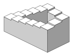
Objects drawn with parallel projection do not appear larger or smaller as they extend closer to or away from the viewer. While advantageous for architectural drawings, where measurements must be taken directly from the image, the result is a perceived distortion, since unlike perspective projection, this is not how our eyes or photography normally work. It also can easily result in situations where depth and altitude are difficult to gauge, as is shown in the illustration to the right.
In this isometric drawing, the blue sphere is two units higher than the red one. However, this difference in elevation is not apparent if one covers the right half of the picture, as the boxes (which serve as clues suggesting height) are then obscured.
This visual ambiguity has been exploited in op art, including "impossible object" drawings. M. C. Escher's Waterfall (1961) is a well-known example, in which a channel of water seems to travel unaided along a downward path, only to then paradoxically fall once again as it returns to its source. The water thus appears to disobey the law of conservation of energy. An extreme example is depicted in the film Inception, where by a forced perspective trick an immobile stairway changes its
Perspective projections
When an object is viewed from different directions and at
different distances, the appearance of the object will be
different. Such view is called perspective view. Perspective
projections mimic what the human eyes see. This is evident
from the two photographs shown in figure 1. In the first
photograph, it appears that the height of the building near to the
observer is taller than the height of the building farther than the
observer though the heights of all these buildings are same.
Similarly the width of the road appears to be shortened for the
region which is away from the observer, though the width of the
road is same along the length. It appears that the two sides
of the road may meet at some far away distance from the
observer. This is a simple representation of the perspective
view.
Perspective views are not important for a manufacturing unit.
They are used to communicate information to non technical
persons. Hence it is very important for commercial purposes. In
perspective projection, all lines of sight start at a single
point. Distance from the observer to the object is finite and
the object is viewed from a single point – projectors are not
parallel.

Figure 1. Photograph of (a) buildings and (b) a road as observed by the human eye or a camera
Before discussing further, it is important to be familiar with the terminology used for the perspective projection
Terminology
Assume an observer viewing the Object as shown in figure 2.
The line of sight is diverging from the observer’s eyes and falling
on the object. Consider the rays meeting the edges of the
object. The rays are intersecting the perspective picture plane
(PPP) which is between the observer and the object, . Referring to
figure 2, the various elements used in perspective projection are
defined below.
Perspective Picture plane (PPP): It is
a vertical projection plane used to obtain the object’s
Perspective.
Station point (s) : It is a point at
which the eyes of the observer are located. S and S’ indicated
respectively the TV and FV of S.
Visual rays: These are the rays of
sight emerging from S and ending at the object’s
corners.
Piercing points: This is the
intersection point of visual rays with the PPP.
Horizon plane (HP): A horizontal plane
passing through S (observer’s eyes).
Horizon line (HL) : The line obtained by the
intersection of HP on PPP.
Perpendicular axis (PA): it is the line drawn
through the station point and perpendicular to the picture plane.
It is also called axis of vision or line of sight.
Ground plane (GP): The real ground or the
imaginary plane parallel to the ground on which the object is
assumed to be resting.
Central plane (CP) : it is a vertical plane
passing through S and perpendicular to PPP
Vanishing point (VP): These are points at
which the edges of the object appear to be converging . This point
is seen at eye level, ie. on HP.

Figure 2. Shows (a) various elements used in perspective projection and (b) the top view and front view showing the station point, GL, HL, PP etc.
Perspective Projection
Methods
Two commonly used methods are
- Visual Ray method
- Vanishing Point method
Common types of perspective Projection
- Parallel Perspective or 1-point perspective : Here one face of the object is kept parallel to the PPP. The edges perpendicular to this face appears to be converging to a VP.
- Angular Perspective or 2-point perspective: One edge of the object is kept parallel to the PPP. Each edges perpendicular to them converges to one of the two VPs.
- Oblique Perspective or 3-point Perspective: Neither an edge nor a face of the object is kept parallel to PPP. Ach edges is seen to be converging to one of the three VPs.
To draw the perspective , the following information is required:
- Top View and Front View (or Side View of) the object. Since the PPP lies between the observer and the object, third angle projection technique is used.
- Orientation and location of the object w.r.t the PPP.
- location of station point S w.r.t to PPP and GL .
Normal practice for location of S is at the normal to the eye level for big objects like buildings and for small objects s is located at such a height that all the three dimensions of the objects are almost visible.
The size of the perspective view depends of the Position of picture plane relative to the object . referring to figure 3,
- When the object is placed behind the picture plane, the perspective will show object reduced in size.
- When the object is placed in front of the picture plane, the perspective will show object enlarged in size.
- When the picture plane coincides with the object, The perspective will show the true size of the object.

Figure 3. Illustrates the size of the perspective view with respect to the position of the picture plane and the object.
- Visual Ray Method
In the visual ray method, the points on the perspective
are obtained by project ting the top view with either
the front view or the side view of the visual rays. The method of
drawing the perspective by visual ray method is illustrated by the
problem below;
Problem 1.
A hexagonal lamina of 45 mm edge lies on the ground. The
corner which is nearest to PPP is 25 mm behind it and an edge
containing that corner is making 50° to PP. The station point is 50
mm in front of PPP. 60 mm above Ground plane and lines in a
central plane which is 80 mm to the left of the corner
nearest to PPP. Draw the perspective view of the lamina by visual
ray method.
Solution: The solution to the problem is
illustrated in figure 4.

Figure 4. Step wise method of drawing the perspective view for problem 1.
The perspective is drawn using the top and Front view.
- First the Front view and top view of the hexagonal lamina is drawn in the third angle projection.
- Construct the hexagon in the top view keeping point a 25 mm above PPP and edge abinclined at 50° to PPP. Label the corners of the hexagon in the top view as a, b, c, d, e, and f.
- Project the front view on to the GL and obtain the points a’, b’ c’, d’ e’ and f’.
- Locate S 80 mm left of point a and 50 mm below PPP.
- Locate S’ 60 mm above GL by drawing projector from S.
- Draw line from S and passing through point a, b, c, d, e, and f in the top view.
- Label the intersection points of these lines PPP as a1, b1, c1, …, f1, respectively.
- Draw line from S’ and passing through point a’, b’ c’, d’ e’ and f’ in the front view.
- Draw vertical projectors from a1, b1, c1, d1, e1 and f1 so as to intersect the lines s’-a’, s’-b’, …, s’-f’ at points A, B, C, D, E, and F. Joint A-B-C-D-E-F to obtain the perspective.
Problem 2.
A square pyramid 5 cm base edge and axis 6 cm high, rest on the
base with one edge of the base parallel to and 3 cm behind the
picture plane. The central plane is 5 cm to the right of the apex.
The station point is 5cm in front of the picture plane and 3 cm
above the ground plane. Draw the perspective of the pyramid
by visual ray method.
Solution: The step wise method of drawing the
perspective view by visual ray method is shown in figure 5.
- First, draw the Top view and Front view by the 3rd angle projection. The top view of the picture plane is PPP. The top view of the edge a-b of the pyramid is 3 cm above PPP. Draw the central plane, i.e. a vertical passing through O in both Front view and top view.
- Locate the station point in the front view and top view. Top view of station point, S is 5 cm towards the right of Central plane and 5 cms below PPP. Front view of station point, S’ is 3 cm
- above GL and passing through the vertical projector through S.
- Draw lines joining the Top view of the station point S to the Top view of the object points a, b, c, d, and o.
- Joint the front view of the station point S’ with the Front view of the object points A,B,C,D, O.
- In the Top view the points at which the visual rays penetrate the picture plane (PPP) are a1, b1, c1, d1 and o1. These are the top views of the perspective points.
- Vertical projectors through these points should pass through the Front views of the perspective points. Hence the vertical projectors through points a1, b1, c1, d1 and o1 should intersect the respective visual rays from S’ in the Front View., These points are A1, B1, C1, D1, and O1 respectively in the Perspective view.
- We can also obtain the perspective view by projections from the Top View and Side view.

Figure 5. Step wise method of drawing the perspective view for problem 1.
Perspective (graphical)

| Part of a series on |
| Graphical projection |
|---|
|
|
Planar[show]
|
|
Other[show]
|
|
Views[show]
|
|
Topics[show]
|
|
|
Perspective (from Latin: perspicere to see through) in the graphic arts is an approximate representation, on a flat surface (such as paper), of an image as it is seen by the eye. The two most characteristic features of perspective are that objects are smaller as their distance from the observer increases; that they are foreshortened, ie that the size of an object's dimensions along the line of sight are relatively shorter than dimensions across the line of sight.
Overview


Linear perspective always works by representing the light that passes from a scene through an imaginary rectangle (the painting), to the viewer's eye. It is similar to a viewer looking through a window and painting what is seen directly onto the windowpane. If viewed from the same spot as the windowpane was painted, the painted image would be identical to what was seen through the unpainted window. Each painted object in the scene is a flat, scaled down version of the object on the other side of the window. Because each portion of the painted object lies on the straight line from the viewer's eye to the equivalent portion of the real object it represents, the viewer cannot perceive (sans depth perception) any difference between the painted scene on the windowpane and the view of the real scene. All perspective drawings assume the viewer is a certain distance away from the drawing. Objects are scaled relative to that viewer. Additionally, an object is often not scaled evenly: a circle often appears as an ellipse and a square can appear as a trapezoid. This distortion is referred to as foreshortening.
Perspective drawings have a horizon line, which is often implied. This line, directly opposite the viewer's eye, represents objects infinitely far away. They have shrunk, in the distance, to the infinitesimal thickness of a line. It is analogous to (and named after) the Earth's horizon.
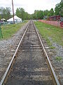
Any perspective representation of a scene that includes parallel lines has one or more vanishing points in a perspective drawing. A one-point perspective drawing means that the drawing has a single vanishing point, usually (though not necessarily) directly opposite the viewer's eye and usually (though not necessarily) on the horizon line. All lines parallel with the viewer's line of sight recede to the horizon towards this vanishing point. This is the standard "receding railroad tracks" phenomenon. A two-point drawing would have lines parallel to two different angles. Any number of vanishing points are possible in a drawing, one for each set of parallel lines that are at an angle relative to the plane of the drawing.
Perspectives consisting of many parallel lines are observed most often when drawing architecture (architecture frequently uses lines parallel to the x, y, and z axes). Because it is rare to have a scene consisting solely of lines parallel to the three Cartesian axes (x, y, and z), it is rare to see perspectives in practice with only one, two, or three vanishing points; even a simple house frequently has a peaked roof which results in a minimum of six sets of parallel lines, in turn corresponding to up to six vanishing points.
In contrast, natural scenes often do not have any sets of parallel lines and thus no vanishing points.
History
|
|
Early history
The earliest art paintings and drawings typically sized many objects and characters hierarchically according to their spiritual or thematic importance, not their distance from the viewer, and did not use foreshortening. The most important figures are often shown as the highest in a composition, also from hieratic motives, leading to the "vertical perspective", common in the art of Ancient Egypt, where a group of "nearer" figures are shown below the larger figure or figures. The only method to indicate the relative position of elements in the composition was by overlapping, of which much use is made in works like the Parthenon Marbles.


Systematic attempts to evolve a system of perspective are usually considered to have begun around the fifth century BC. in the art of Ancient Greece, as part of a developing interest in illusionism allied to theatrical scenery and detailed withinAristotle's Poetics as 'skenographia': Using flat panels on a stage to give the illusion of depth.[2] The philosophers Anaxagorasand Democritus worked out geometric theories of perspective for use with skenographia. Alcibiades had paintings in his house designed based on skenographia, thus this art was not confined merely to the stage. Euclid's Optics introduced a mathematical theory of perspective; however, there is some debate over the extent to which Euclid's perspective coincides with a modern mathematical definition of perspective.
By the later periods of antiquity, artists, especially those in less popular traditions, were well aware that distant objects could be shown smaller than those close at hand for increased illusionism, but whether this convention was actually used in a work depended on many factors. Some of the paintings found in the ruins of Pompeii show a remarkable realism and perspective for their time;[3] it has been claimed that comprehensive systems of perspective were evolved in antiquity, but most scholars do not accept this. Hardly any of the many works where such a system would have been used have survived. A passage inPhilostratus suggests that classical artists and theorists thought in terms of "circles" at equal distance from the viewer, like a classical semi-circular theatre seen from the stage.[4] The roof beams in rooms in the Vatican Virgil, from about 400 AD, are shown converging, more or less, on a common vanishing point, but this is not systematically related to the rest of the composition.[5] In the Late Antique period use of perspective techniques declined. The art of the new cultures of the Migration Period had no tradition of attempting compositions of large numbers of figures and Early Medieval art was slow and inconsistent in relearning the convention from classical models, though the process can be seen underway in Carolingian art.
European Medieval artists were aware of the general principle of varying the relative size of elements according to distance, but even more than classical art was perfectly ready to override it for other reasons. Buildings were often shown obliquely according to a particular convention. The use and sophistication of attempts to convey distance increased steadily during the period, but without a basis in a systematic theory. Byzantine art was also aware of these principles, but also had the reverse perspective convention for the setting of principal figures.
Giotto attempted drawings in perspective using an algebraic method to determine the placement of distant lines. One of Giotto's first uses of his algebraic method of perspective was Jesus Before Caiaphas. Although the picture does not conform to the modern, geometrical method of perspective, it does give a considerable illusion of depth, and was a large step forward in Western art.[citation needed]
With the exception of dice,[6] heraldry typically ignores perspective in the treatment of charges, though sometimes in later centuries charges are specified as in perspective.

Renaissance : Mathematical basis
|
|
By the 14th century, Alhazen's Book of Optics was available in Italian translation, entitled Deli Aspecti. The Renaissance artist Lorenzo Ghiberti relied heavily upon this work, quoting it "verbatim and at length" while framing his account of art and its aesthetic imperatives in the “Commentario terzo.” Alhazen's work was thus "central to the development of Ghiberti's thought about art and visual aesthetics" and "may well have been central to the development of artificial perspective in early Renaissance Italian painting."[7][8][citation needed]
 |
|
In about 1413 a contemporary of Ghiberti, Filippo Brunelleschi, demonstrated the geometrical method of perspective, used today by artists, by painting the outlines of various Florentine buildings onto a mirror. When the building's outline was continued, he noticed that all of the lines converged on the horizon line. According to Vasari, he then set up a demonstration of his painting of the Baptistery in the incomplete doorway of the Duomo. He had the viewer look through a small hole on the back of the painting, facing the Baptistery. He would then set up a mirror, facing the viewer, which reflected his painting. To the viewer, the painting of the Baptistery and the Baptistery itself were nearly indistinguishable.[citation needed]
Soon after, nearly every artist in Florence and in Italy used geometrical perspective in their paintings,[12] notably Masolino da Panicale andDonatello. Donatello started sculpting elaborate checkerboard floors into the simple manger portrayed in the birth of Christ. Although hardly historically accurate, these checkerboard floors obeyed the primary laws of geometrical perspective: the lines converged approximately to a vanishing point, and the rate at which the horizontal lines receded into the distance was graphically determined. This became an integral part of Quattrocento art. Melozzo da Forlì first used the technique of upward foreshortening (in Rome, Loreto, Forlì and others), and was celebrated for that. Not only was perspective a way of showing depth, it was also a new method of composing a painting. Paintings began to show a single, unified scene, rather than a combination of several.


As shown by the quick proliferation of accurate perspective paintings in Florence, Brunelleschi likely understood (with help from his friend the mathematician Toscanelli),[13] but did not publish, the mathematics behind perspective. Decades later, his friend Leon Battista Alberti wrote De pictura (1435/1436), a treatise on proper methods of showing distance in painting. Alberti's primary breakthrough was not to show the mathematics in terms of conical projections, as it actually appears to the eye. Instead, he formulated the theory based on planar projections, or how the rays of light, passing from the viewer's eye to the landscape, would strike the picture plane (the painting). He was then able to calculate the apparent height of a distant object using two similar triangles. The mathematics behind similar triangles is relatively simple, having been long ago formulated by Euclid. In viewing a wall, for instance, the first triangle has a vertex at the user's eye, and vertices at the top and bottom of the wall. The bottom of this triangle is the distance from the viewer to the wall. The second, similar triangle, has a point at the viewer's eye, and has a length equal to the viewer's eye from the painting. The height of the second triangle can then be determined through a simple ratio, as proven by Euclid. Alberti was also trained in the science of optics through the school of Padua and under the influence of Biagio Pelacani da Parma who studied Alhazen's Optics (see what was noted above in this regard with respect to Ghiberti).
Piero della Francesca elaborated on Della Pittura in his De Prospectiva Pingendi in the 1470s. Alberti had limited himself to figures on the ground plane and giving an overall basis for perspective. Della Francesca fleshed it out, explicitly covering solids in any area of the picture plane. Della Francesca also started the now common practice of using illustrated figures to explain the mathematical concepts, making his treatise easier to understand than Alberti's. Della Francesca was also the first to accurately draw the Platonic solids as they would appear in perspective.
Perspective remained, for a while, the domain of Florence. Jan van Eyck, among others, was unable to create a consistent structure for the converging lines in paintings, as in London's The Arnolfini Portrait, because he was unaware of the theoretical breakthrough just then occurring in Italy. However he achieved very subtle effects by manipulations of scale in his interiors. Gradually, and partly through the movement of academies of the arts, the Italian techniques became part of the training of artists across Europe, and later other parts of the world.
The culmination of these Renaissance traditions finds its ultimate synthesis in the research of the architect, geometer, and optician Girard Desargues on perspective, optics and projective geometry.
Present : Computer graphics
3-D computer games and ray-tracers often use a modified version of perspective. Like the painter, the computer program is generally not concerned with every ray of light that is in a scene. Instead, the program simulates rays of light traveling backwards from the monitor (one for every pixel), and checks to see what it hits. In this way, the program does not have to compute the trajectories of millions of rays of light that pass from a light source, hit an object, and miss the viewer.[dubious – discuss]
CAD software, and some computer games (especially games using 3-D polygons) use linear algebra, and in particular matrix multiplication, to create a sense of perspective. The scene is a set of points, and these points are projected to a plane (computer screen)[dubious – discuss] in front of the view point (the viewer's eye). The problem of perspective is simply finding the corresponding coordinates on the plane corresponding to the points in the scene. By the theories of linear algebra, a matrix multiplication directly computes the desired coordinates, thus bypassing any descriptive geometry theorems used in perspective drawing.[dubious – discuss].
Types of perspective
Of the many types of perspective drawings, the most common categorizations of artificial perspective are one-, two- and three-point. The names of these categories refer to the number of vanishing points in the perspective drawing.
One-point perspective

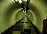
A drawing has one-point perspective when it contains only one vanishing point on the horizon line. This type of perspective is typically used for images of roads, railway tracks, hallways, or buildings viewed so that the front is directly facing the viewer. Any objects that are made up of lines either directly parallel with the viewer's line of sight or directly perpendicular (the railroad slats) can be represented with one-point perspective. These parallel lines converge at the vanishing point.
One-point perspective exists when the painting plate (also known as the picture plane) is parallel to two axes of a rectilinear (or Cartesian) scene – a scene which is composed entirely of linear elements that intersect only at right angles. If one axis is parallel with the picture plane, then all elements are either parallel to the painting plate (either horizontally or vertically) or perpendicular to it. All elements that are parallel to the painting plate are drawn as parallel lines. All elements that are perpendicular to the painting plate converge at a single point (a vanishing point) on the horizon.
- Examples of one-point perspective
-

-
-

-

-

-
-

-

Two-point perspective


A drawing has two-point perspective when it contains two vanishing points on the horizon line. In an illustration, these vanishing points can be placed arbitrarily along the horizon. Two-point perspective can be used to draw the same objects as one-point perspective, rotated: looking at the corner of a house, or looking at two forked roads shrink into the distance, for example. One point represents one set of parallel lines, the other point represents the other. Looking at a house from the corner, one wall would recede towards one vanishing point, the other wall would recede towards the opposite vanishing point.
Two-point perspective exists when the painting plate is parallel to a Cartesian scene in one axis (usually the z-axis) but not to the other two axes. If the scene being viewed consists solely of a cylinder sitting on a horizontal plane, no difference exists in the image of the cylinder between a one-point and two-point perspective.
Two-point perspective has one set of lines parallel to the picture plane and two sets oblique to it. Parallel lines oblique to the picture plane converge to a vanishing point,which means that this set-up will require two vanishing points.

Three-point perspective

Three-point perspective is usually used for buildings seen from above (or below). In addition to the two vanishing points from before, one for each wall, there is now one for how those walls recede into the ground. This third vanishing point will be below the ground. Looking up at a tall building is another common example of the third vanishing point. This time the third vanishing point is high in space.
Three-point perspective exists when the perspective is a view of a Cartesian scene where the picture plane is not parallel to any of the scene's three axes. Each of the three vanishing points corresponds with one of the three axes of the scene. One-point, two-point, and three-point perspectives appear to embody different forms of calculated perspective. The methods required to generate these perspectives by hand are different. Mathematically, however, all three are identical: The difference is simply in the relative orientation of the rectilinear scene to the viewer.
Four-point perspective
Four-point perspective, also called infinite-point perspective, is the curvilinear variant of two-point perspective. As the result when made into an infinite point version (i.e. when the amount of vanishing points exceeds the minimum amount required), a four point perspective image becomes a panorama that can go to a 360 degree view and beyond – when going beyond the 360 degree view the artist might depict an "impossible" room as the artist might depict something new when it's supposed to show part of what already exists within those 360 degrees. This elongated frame can be used both horizontally and vertically and when used vertically can be described as an image that depicts both a worm's- and bird's-eye view of a scene at the same time.
Like all other foreshortened variants of perspective (respectively one- to six-point perspective), it starts off with a horizon line, followed by four equally spaced vanishing points to delineate four vertical lines.
The vanishing points made to create the curvilinear orthogonals are thus made ad hoc on the four vertical lines placed on the opposite side of the horizon line. The only dimension not foreshortened in this type of perspective is the rectilinear and parallel lines perpendicular to the horizon line – similar to the vertical lines used in two-point perspective.
Zero-point perspective
Because vanishing points exist only when parallel lines are present in the scene, a perspective with no vanishing points ("zero-point" perspective) occurs if the viewer is observing a non-linear scene. [14] The most common example of a nonlinear scene is a natural scene (e.g., a mountain range) which frequently does not contain any parallel lines. A perspective without vanishing points can still create a sense of depth.
Other varieties of linear perspective
One-point, two-point, and three-point perspective are dependent on the structure of the scene being viewed. These only exist for strict Cartesian (rectilinear) scenes. By inserting into a Cartesian scene a set of parallel lines that are not parallel to any of the three axes of the scene, a new distinct vanishing point is created. Therefore, it is possible to have an infinite-point perspective if the scene being viewed is not a Cartesian scene but instead consists of infinite pairs of parallel lines, where each pair is not parallel to any other pair. Zero point perspective view is also known as elevation of any object
Foreshortening


Foreshortening is the visual effect or optical illusion that causes an object or distance to appear shorter than it actually is because it is angled toward the viewer. Additionally, an object is often not scaled evenly: a circle often appears as an ellipse and a square can appear as a trapezoid.
Although foreshortening is an important element in art where visual perspective is being depicted, foreshortening occurs in other types of two-dimensional representations of three-dimensional scenes. Some other types where foreshortening can occur include oblique parallel projectiondrawings. Foreshortening also occurs when imaging rugged terrain using a synthetic aperture radar system.[citation needed]
In painting, foreshortening in the depiction of the human figure was perfected in the Italian Renaissance, and the The Lamentation over the Dead Christ by Andrea Mantegna (1480s) is one of the most famous of a number of works that show off the new technique, which thereafter became a standard part of the training of artists.
Methods of construction
Several methods of constructing perspectives exist, including:
- Freehand sketching (common in art)
- Graphically constructing (once common in architecture)
- Using a perspective grid
- Computing a perspective transform (common in 3D computer applications)
- Mimicry using tools such as a proportional divider (sometimes called a variscaler)
Example


One of the most common, and earliest, uses of geometrical perspective is a checkerboard floor. It is a simple but striking application of one-point perspective. Many of the properties of perspective drawing are used while drawing a checkerboard. The checkerboard floor is, essentially, just a combination of a series of squares. Once a single square is drawn, it can be widened or subdivided into a checkerboard. Where necessary, lines and points will be referred to by their colors in the diagram.
To draw a square in perspective, the artist starts by drawing a horizon line (black) and determining where the vanishing point (green) should be. The higher up the horizon line is, the lower the viewer will appear to be looking, and vice versa. The more off-center the vanishing point, the more tilted the square will be. Because the square is made up of right angles, the vanishing point should be directly in the middle of the horizon line. A rotated square is drawn using two-point perspective, with each set of parallel lines leading to a different vanishing point.
The foremost edge of the (orange) square is drawn near the bottom of the painting. Because the viewer's picture plane is parallel to the bottom of the square, this line is horizontal. Lines connecting each side of the foremost edge to the vanishing point are drawn (in grey). These lines give the basic, one point "railroad tracks" perspective. The closer it is the horizon line, the farther away it is from the viewer, and the smaller it will appear. The farther away from the viewer it is, the closer it is to being perpendicular to the picture plane.
A new point (the eye) is now chosen, on the horizon line, either to the left or right of the vanishing point. The distance from this point to the vanishing point represents the distance of the viewer from the drawing. If this point is very far from the vanishing point, the square will appear squashed, and far away. If it is close, it will appear stretched out, as if it is very close to the viewer.
A line connecting this point to the opposite corner of the square is drawn. Where this (blue) line hits the side of the square, a horizontal line is drawn, representing the farthest edge of the square. The line just drawn represents the ray of light traveling from the farthest edge of the square to the viewer's eye. This step is key to understanding perspective drawing. The light that passes through the picture plane obviously can not be traced. Instead, lines that represent those rays of light are drawn on the picture plane. In the case of the square, the side of the square also represents the picture plane (at an angle), so there is a small shortcut: when the line hits the side of the square, it has also hit the appropriate spot in the picture plane. The (blue) line is drawn to the opposite edge of the foremost edge because of another shortcut: since all sides are the same length, the foremost edge can stand in for the side edge.
Original formulations used, instead of the side of the square, a vertical line to one side, representing the picture plane. Each line drawn through this plane was identical to the line of sight from the viewer's eye to the drawing, only rotated around the y-axis ninety degrees. It is, conceptually, an easier way of thinking of perspective. It can be easily shown that both methods are mathematically identical, and result in the same placement of the farthest side.
Limitations
Plato was one of the first to discuss the problems of perspective. "Thus (through perspective) every sort of confusion is revealed within us; and this is that weakness of the human mind on which the art of conjuring and of deceiving by light and shadow and other ingenious devices imposes, having an effect upon us like magic... And the arts of measuring and numbering and weighing come to the rescue of the human understanding – there is the beauty of them – and the apparent greater or less, or more or heavier, no longer have the mastery over us, but give way before calculation and measure and weight?"

Perspective images are calculated assuming a particular vanishing point. In order for the resulting image to appear identical to the original scene, a viewer of the perspective must view the image from the exact vantage point used in the calculations relative to the image. This cancels out what would appear to be distortions in the image when viewed from a different point. These apparent distortions are more pronounced away from the center of the image as the angle between a projected ray (from the scene to the eye) becomes more acute relative to the picture plane. In practice, unless the viewer chooses an extreme angle, like looking at it from the bottom corner of the window, the perspective normally looks more or less correct. This is referred to as "Zeeman's Paradox."[16] It has been suggested that a drawing in perspective still seems to be in perspective at other spots because we still perceive it as a drawing, because it lacks depth of field cues.[17]
For a typical perspective, however, the field of view is narrow enough (often only 60 degrees) that the distortions are similarly minimal enough that the image can be viewed from a point other than the actual calculated vantage point without appearing significantly distorted. When a larger angle of view is required, the standard method of projecting rays onto a flat picture plane becomes impractical. As a theoretical maximum, the field of view of a flat picture plane must be less than 180 degrees (as the field of view increases towards 180 degrees, the required breadth of the picture plane approaches infinity).
To create a projected ray image with a large field of view, one can project the image onto a curved surface. To have a large field of view horizontally in the image, a surface that is a vertical cylinder (i.e., the axis of the cylinder is parallel to the z-axis) will suffice (similarly, if the desired large field of view is only in the vertical direction of the image, a horizontal cylinder will suffice). A cylindrical picture surface will allow for a projected ray image up to a full 360 degrees in either the horizontal or vertical dimension of the perspective image (depending on the orientation of the cylinder). In the same way, by using a spherical picture surface, the field of view can be a full 360 degrees in any direction (note that for a spherical surface, all projected rays from the scene to the eye intersect the surface at a right angle).
Just as a standard perspective image must be viewed from the calculated vantage point for the image to appear identical to the true scene, a projected image onto a cylinder or sphere must likewise be viewed from the calculated vantage point for it to be precisely identical to the original scene. If an image projected onto a cylindrical surface is "unrolled" into a flat image, different types of distortions occur. For example, many of the scene's straight lines will be drawn as curves. An image projected onto a spherical surface can be flattened in various ways:
- An image equivalent to an unrolled cylinder
- A portion of the sphere can be flattened into an image equivalent to a standard perspective
- An image similar to a fisheye photograph
Perspective projection -2
Drawing the perspective by Vanishing point method
Vanishing points are imaginary points at infinite distance away
from the station point. This is the point at which the visual rays
from the station point to the infinitely distant
vanishing point pierces the Picture plane (PPP).
Vanishing point of the
line AB (line ab in the top
view), lying on the ground and inclined at an angle to the picture
plane can be obtained by drawing a line parallel to its
top view and passing through the station point s. The intersection
of this line with the PPP, (i.e. v) is the top view of the
vanishing point. The front view V is obtained by projecting point v
to the Horizon line(HL) as shown in figure 1.
- Perspective of all horizontal lines, when produced, pass through their respective vanishing points on the horizon line.
- Perspective of all horizontal line which are parallel to each other converge to a vanishing point on the horizon line.
- Perspectives of all lines perpendicular to the picture plane converge to the centre of vision on the horizon line.
- Perspective of lines parallel to the picture plane will have no vanishing points since these are parallel to the original lines and remain horizontal.
- Perspective of vertical lines are vertical.

Figure 1. Illustration of vanishing point of a line.
The method of drawing perspective view by vanishing point method is discussed below:
- Parallel Perspective or 1-point perspective
Here one face of the object is kept parallel to and in the PPP as shown in figure 2. Since this face is in the PPP, the edges in the front view will be true dimensions. The edges perpendicular to this face appears to be converging to a VP. Draw visual rays from the station points to the object points in both TP and FV. Draw vertical projectors from the piercing points in the top view to meet the corresponding visual rays in the front view.

Figure 2. 1-point perspective view of a rectangular prism with one face in PPP.
2.Angular Perspective or 2-point perspective
One edge of the object is kept parallel to the PPP., as shown by line AE of figure 3. The two faces, ABFE and ADHE, sharing the edge AE are inclined to the PPP. Each edges perpendicular to the edge AE and parallel to PPP will converge to two vanishing points on HL on either side of the observer. To obtain the vanishing points, draw lines parallel to edge ab and ad and passing through the station point. The intersection of these line with PPP are respectively v1 and v2. From v1 and v2, drop vertical projectors to HL to obtain the vanishing points V1 and V2 respectively. Since edge AE is in PPP, the front view of this edge (AE) will be its true length. Draw lines from V1 and V2 and passing through points E and A in the Front view . To obtain the perspective for the edges BF, CG and DH, join the respective points in the top view with the station point s. label the points where these rays pierces the PPP as a1, b1, c1, d1, e1, f1 and g1. Draw vertical projectors from d1 and h1 to intersect the lines joining V1 to A and E in the front view. Similarly points B and F are obtained by drawing the vertical projectors from b1 and f1 and intersecting the lines joining V2 with A and B in the front view. Points C and G are obtained by drawing the vertical projectors from c1 and g1 in the top view and the respective intersection of the lines joining V2 to D and H (or lines joining V1 to points B and F.

Figure 3. Angular projection perspective view of a rectangular prism .
Line of heights
When a line is in the picture plane, it is seen in its true length
in perspective. The top view and Front view of a rectangle
ABCD, shown in figure 4, whose surface is vertical and
inclined to the picture plane is shown as abcd and ABCD. DC
is on the ground plane and edge AD is in the picture plane.
In the perspective view , edge A’D’ is equal to the true
length AD. Edge B’C’ is shorter than BC. The length B’C’ is derived
from A’D’ and V.

Figure 4. Illustrating the significance of line of height
If we consider rectangle EBFC inside rectangle ABCD, the length
E’F’ is shorter than EF in the perspective view.
B’C’ and E’F’ can be obtained as follows.
Join s to ef and bc. From point of intersection of these lines with
PPP, draw vertical lines to intersect the lines joining V and
A’D’.
If we consider rectangle EBFC inside rectangle ABCD, the length
E’F’ is shorter than EF in the perspective view.
B’C’ and E’F’ can be obtained as follows.
Join s to ef and bc. From point of intersection of these lines with
PPP, draw vertical lines to intersect the lines joining V
with A’ and D’.
E’ F’ and B’C’ are called the line of heights (LOH) of
EF and BC. LOH helps us to draw perspective of the
surfaces behind or in front of PPP.
Worked out problems:
Problem 1: The top view and Front view of a triangular prism resting on its rectangular face on the ground is shown in figure 5 (a). A triangular face is parallel to and 15 mm behind PPP. The observer is viewing the object from a point 50 mm above the ground and 30 mm in front of the PPP. The central plane (CP) is 90 mm towards the left of the axis of the prism. Draw the perspective view of the prism.
Solution: The perspective view is shown in figure 5 (b). The step wise procedure of obtaining the perspective view is as follows:
- Draw the front view and top view of the triangular prism.
- Draw the perspective picture plane (PPP) 15 mm behind PPP (below the edge abc in the top view).
- Draw HL 50 mm above GL.
- Locate station point S and S’ in the top view and front view respectively. S is 30 mm below line PPP and 90 mm towards left of CP (left of edge cf). S’ is in HL and passing through the verticalprojector through S.
- In the top view, draw lines from S to meet the corners of the prism (i.e. points s, b, c, d, e, and f). Mark the intersection of these lines with PPP as a1, b1, c1, d1, e1, and f1.
- In the front view, draw lines from S’ to a’, b’, and c’.
- Draw vertical projectors from points a1, b1, c1, d1, e1, and f1 such that they intersect the lines joining S’ with a’, b’ and c’ to obtain the points A, B, C, D, E, and F of the perspective view..

Figure 5. Showing the solution to the problem 1.
Problem 2. The top view and Front view of a hut is shown in figure 6 (a). The front face of the hut lies in the picture plane. The station point is 60 mm in front of the PPP and 25 mm above the Ground plane. The central plane is 75 mm towards the right of the vertical axis of the hut. Draw the perspective projection of the hut.
Solution: The solution for the problem is shown in figure 6(b). The step wise procedure for drawing the perspective view is discussed below:
- Draw the Front view and top view of the hut by the 3rd angle projection technique.
- Draw PPP with face abcde in PPP. In the top view, locate station point S 60 mm below PPP and 75 mm towards the left of CP (left of edge bg).
- Locate station point S’ in the front view by drawing vertical projector from S and 25 mm above GL.
- Join S to the corner points f, g, h, j, and k. The points 1, 2 and 3 are the points where these line pierces the PPP.
- In the front view, draw lines joining S’ with corner points D, E, A, B, and C.
- Draw vertical projectors from points 1, 2, and 3 to meet these lines to obtain the points J’, K’, F’, G’ and C’, respectively. Join the edges to obtain the perspective view.

Figure 6. Illustrates the solution for problem 2.
Axonometric
projection-
Axonometric projection is a
parallel projection technique used to create a pictorial drawing of
an object by rotating the object along one or more of its axes
relative to the plane of projection (or the picture plane).
Axonometric projection is one of the four principal projection
techniques: multiview, axonometric, oblique and perspective
projection (Figure-1). In multi view, axonometric, and oblique
projections, the observer is theoretically infinitely far away from
the projection plane. In addition, the lines of sight are parallel
to each other and perpendicular to the plane of projection.
The main difference between a multiview drawing and an
axonometric drawing are that, in a multiview, only two dimensions
of an object are visible in each view and hence more than one view
is required to define the object. In an axonometric drawing, the
object is rotated about an axis to show all three dimensions, and
only one view is required.

Figure 1. illustrates the four principle projection techniques.
Isometric projection is a type of
pictorial projection in which the dimensions along the three axes
of the solid are shown in one view. It is one of the three types
of axonometric projection
In axonometric drawing, one axis of
space is shown vertical and depending on the exact angle at which
the view deviates from the orthogonal, axonometric projections are
generally three types: (a) trimetric projection, (b)
dimetric projection, and (c) isometric projection.. This is
illustrated in figure 2.
- In trimetric projection, the direction of viewing is such that all of the three axes of space appear unequally foreshortened. The scale along each of the three axes and the angles among them are determined separately as dictated by the angle of viewing. Trimetric perspective is seldom used
- In dimetric projection, the direction of viewing is such that two of the three axes of space appear equally shortened, of which the attendant scale and angles of presentation are determined according to the angle of viewing; the scale of the third direction (vertical) is determined separately. When two of the three angles are equal, the drawing is classified as a dimetric projection. Dimetric drawings are less pleasing to the eye, but are easier to produce than trimetric drawings
- In isometric projection, the most commonly used form of axonometric projection in engineering drawing. Here all three angles are equal. The isometric is the least pleasing to the eye, but is the easiest to draw and dimension.

Figure 2. Shows the three types of axinometric drawing. The angles determine the type of axinometric drawing.
Isometric Axonometric
Projections
An isometric projection is a true
representation of the isometric view of an object. An
isometric view of an object is created by rotating the object 45°
about a vertical axis, then tilting the object (see figure 3,
in this case, a cube) forward until the body diagonal (AB)
appears as a point in the front view. The angle the cube is
tilted forward is 35° 16’. The 3 axes that meet at A, B form equal
angles of 120° and are called the isometric axes. Each
edge of the cube is parallel to one of the isometric axes.
Line parallel to one of the legs of the isometric axis is an
isometric line. Planes of the cube faces & all planes
parallel to them are isometric planes

Figure 3. Rotation of the object with respect to the projection plane result in isometric projection.
The forward tilt of the cube causes the edges and planes of the cube to become shortened as it is projected onto the picture plane. The lengths of the projected lines are equal to the cosine of 35° 16’, or 0.81647 times the true length. In other words, the projected lengths are approximately 80% of the true lengths. A drawing produced using a scale of 0.816 is called anisometric projection and is a true representation of the object. However, if the drawing is produced using full scale, it is called an isometric drawing, which is the same proportion as an isometric projection, but is larger by a factor of 1.23 to 1. Figure 4. Illustrates the isometric projection and isometric drawing. Isometric drawings are almost always preferred over isometric projection for engineering drawings, because they are easier to produce. An isometric drawing is an axonometric pictorial drawing for which the angle between each axis equals 120° and the scale used is full scale.

Figure 4 Shows the (a) isometric projection and (b) isometric drawing (or view) of a cuboid.
While drawing isometric projection, an Isometric scale is to be constructed for convenience and all the measurements are to be taken from this scale. As shown in figure 5, isometric scale is produced by positioning a regular scale at 45 ° to the horizontal and projecting lines vertically to a 30° line.

Figure 5. illustrates the construction of an isometric scale.

i.e. isometric length = 82% (approximately)
sometric axes can be positioned in a number of ways to create different views of the same object. Figure 6(a) is a regular isometric, in which the viewpoint is looking down on the top of the object. In a regular isometric, the axes at 30° to the horizontal are drawn upward from the horizontal. In the reversed axis isometric, as shown in figure 6(b), the viewpoint is looking up on the bottom of the object, and the 30° axes are drawn downward from the horizontal. Figure 6(c)&(d) show the long axis isometric, where the viewpoint is looking from the right or from the left of the object, and one axis is drawn at 60 ° to the horizontal. While drawing the Isometric view, first the view point will have to be decided for obtaining the maximum technical information.

Figure 6. shows different isometric axis depending on the direction of view point.
Isometric axes and non-isometric axes
Figure 7(a) illustrates the
isometric axes, non-isometric axes and isometric planes. In an
isometric drawing, true length distances can only be measured along
isometric lines. i.e. lines that run parallel to any of the
isometric axes. Any line that does not run parallel to an isometric
axis is called a non-isometric line. Non-isometric lines include
inclined and oblique lines and cannot be measured directly. Instead
they must be created by locating two end points. Figure 7(b) is an
isometric drawing of a cube. The three faces of the isometric
cube are isometric planes, because they are parallel to the
isometric surfaces formed by any two adjacent isometric axes.
Planes that are not parallel to any isometric plane are
called non-isometric planes sa shown in figure 7(a).

Figure 7. showing isometric axes, non-isometric axes and isometric planes.
Hidden Lines, Center
Lines and Dimensions
In isometric drawings, hidden lines
are omitted unless they are absolutely necessary to completely
describe the object. Most isometric drawings will not have hidden
lines. To avoid using hidden lines, choose the most descriptive
viewpoint. However, if an isometric viewpoint cannot be found which
clearly depicts all the major features, hidden lines may be used.
eg. Figure 8(a). Centerlines are drawn only for showing symmetry or
for dimensioning. Normally, centerlines are not shown, because many
isometric drawings are used to communicate to non-technical people
and not for engineering purposes.

Figure 8 showing hidden lines and centre lines.
Dimension lines, extension lines, and lines being dimensioned shall lie in the same plane. All dimensions and notes should be unidirectional, reading from the bottom of the drawing upward and should be located outside the view whenever possible. The texts are read from the bottom, using horizontal guidelines as shown in Figure 9.

Figure 9 showing the procedure of using dimension lines, extension lines and text.
Isometric view of some standard shapes
1.Square
Consider a square ABCD with a 30 mm side shown in Fig. If the square lies in the vertical plane, it will appear as a rhombus with a 30 mm side in isometric view as shown in Fig. (a) or (b), depending on its orientation, i.e., right-hand vertical face or left-hand vertical face. If the square lies in the horizontal plane (like the top face of a cube), it will appear as in Fig.(c). The sides AB and AD, both, are inclined to the horizontal reference line at 30°.

Figure 10. Isometric views of a square.
2.Rectangle
A rectangle appears as a parallelogram in isometric view as shown in figure 11.. Three versions are possible depending on the orientation of the rectangle, i.e., right-hand vertical face, left-hand vertical face or horizontal face.

Figure 11. Isometric views of a rectangle.
3.Triangle
A triangle of any type can be easily obtained in isometric view as explained below. First enclose the triangle in rectangle ABCD. Obtain parallelogram ABCD of the rectangle as shown in Fig. 12(a) or (b) or (c). Then locate point 1 in the parallelogram such that C–1 in the parallelogram is equal to C–1 in the rectangle. A–B–1 represents the isometric view of the triangle.

Figure 12. Method of obtaining the isometric views of a triangle.
4.Pentagon
Enclose the given pentagon in a rectangle and obtain the parallelogram as in Fig. 13 (a) or (b) or (c). Locate points 1, 2, 3, 4 and 5 on the rectangle and mark them on the parallelogram. The distances A–1, B–2, C–3, C–4 and D–5 in isometric drawing are same as the corresponding distances on the pentagon enclosed in the rectangle since the edges of the rectangle are isometric axes.

Figure 13. Method of obtaining the isometric views of a pentagon.
5.Circle
The isometric view or isometric
projection of a circle is an ellipse. It is obtained by using
four-centre method explained below and illustrated in Figure
14.
Four-Centre
Method: First, enclose the
given circle into a square ABCD. Draw
rhombus ABCDas an isometric view of the square. Join
the farthest corners of the rhombus,
i.e., A and C. Obtain midpoints 3
and 4 of
sides CD and AD respectively.
Locate points 1 and 2 at the intersection
of AC with B–3
and B–4 respectively. Now with 1 as a centre and
radius 1–3, draw a small arc 3–5. Draw another arc 4–6 with same
radius but 2 as a centre. With B as a centre and
radius B–3, draw an arc 3–4. Draw another arc 5–6
with same radius but with D as a
centre.

Figure 14. Method of obtaining the isometric views of a circle by four-centre method.
6.Isometric view of irregular Shape
The method of drawing the isometric view of an irregular shape 1–2–3–4–5–6–7 is illustrated in Figure 15. First the figure is enclosed in a rectangle. The parallelogram is obtained in isometric for the rectangle as shown. The distances B–2, D–2, C–3, E–3, G–4, F–4, H–5, H–6 and A–7 has the same length as in original shape since they are along the isometric axis. The points 1 to 7 are located by travelling along the isometric lines. After locating the points, the points are joined for lines which lie along non-isometric lines viz. 1-2, 2-3, 3-G, 6-5, 7-6.

Figure 15. Method of obtaining the isometric views of an irregular shape.
Isometric
Projections-2
The most convenient method of
drawing the isometric view of any solid object is by the boxing
method. In this the object is considered to be placed in a
rectangular box having dimensions with maximum dimensions of the
object along the three axes. The edges of the rectangular box are
the isometric axes and the surfaces of the rectangular box are the
isometric planes.
The four basic steps for creating an isometric drawing are:
- Positioning the object. Determine the isometric viewpoint that clearly depicts maximum features of the object
- Once the object is positioned and the view point is decided, draw the isometric axes which will produce that view-point.
- Construct isometric planes, using the overall width (W), height (H), and depth (D) of the object, such that the object will be totally enclosed in a box.
- Locate details on the isometric planes. Darken all visible lines, and eliminate hidden lines unless absolutely necessary to describe the object.
Figure 1 Shows the multi-view drawing of an object. The figure illustrates the isometric view of the object while positioning using the regular isometric and reverse isometric view points. For this object, regular isometric will provide maximum information regarding the object compared to the reverse isometric.

Figure 1. The isometric views using regular isometric and reverse isometric view points.
The step wise procedure of drawing of isometric views of objects are presented in the subsequent examples.
Example -1: Drawing isometric
planes
The step wise procedure for drawing
isometric view of an object having isometric planes only are
shown in figure 2.

Figure 2. Step wise procedure of drawing the isometric view of the object
Step 1. Determine the
desired view of the object. Here the object will be viewed
from above (regular isometric). The isometric axes is then drawn as
shown in step-1.
Step 2. Construct the front
isometric plane using W and H dimensions. Width dimensions are
drawn along 30o lines from the horizontal. Height dimensions are
drawn as vertical lines.
Step 3. Construct the top
isometric plane using the W and D dimensions. Both W and D
dimensions are drawn along 30o lines from the
horizontal.
Step 4. Construct
the right side isometric plane using D and H dimensions. Depth
dimensions are drawn along 30o lines and height dimensions are
drawn as vertical lines.
Step 5. Transfer
some distances for the various features from the multi-view drawing
to the isometric lines that make up the isometric rectangle on the
front and top planes of the isometric box. e.g.
distance A is measured from the multi-view drawing./ It is then
transferred along the width line in the front plane of the
isometric rectangle. Draw the details of the block by drawing
isometric lines between the points transferred from the multi-view
drawing. e.g., the notch is taken out of the block by
locating its position on the front and the top planes of the
isometric box.
Step 6. Transfer
the remaining features from the multi-view drawing to the isometric
drawing. Block in the details by connecting endpoints of the
measurements taken from the multi-view drawing.
Step 7. Darken
all visible lines and erase or lighten the construction lines to
complete the isometric drawing of the object
Example 2.
Drawing Non-Isometric Lines
Non-isometric lines will be the
edges of inclined or oblique planes of an object as represented in
a multi-view drawing. It is not possible to measure the length or
angle from an inclined or oblique line in a multi-view drawing and
then transferring these distances to draw the line in an isometric
drawing. Instead, non-isometric lines must be drawn by locating the
two end points of the lines on isometric lines and then connecting
these end points with a line. The process used is called
offset measurement, which is a method of locating one point by
projecting another point. Figure 3. Illustrates the step wise
procedure of drawing the isometric view of an object having
inclined or oblique planes.

Figure 3. Step wise procedure of drawing the isometric view of the object having non-isometric planes.
Step 1. Determine the
desired view of the object, then draw the isometric axes.
Here it is preferred that the object be viewed from above,
and the axis shown in Figure A is used.
Step 2. Construct the front
isometric plane using W and H dimensions.
Step 3. Construct the top
isometric plane using the W and D dimensions.
Step 4. Construct the right
side isometric plane using D and H dimensions.
Step 5. Transfer the distances
for A and C from the multi-view drawing to the top and right side
isometric rectangles. Draw line MN across the top face of the
isometric box. Draw an isometric construction line from the
endpoint marked for distance C. This projects the distance C along
the width of the box.
Step 6. Along these isometric
construction lines, mark off the distance B, thus locating points O
and P. Connect points OP.
Step 7. Connect points MO and
NP to draw the non-isometric lines.
Example 3: To locating the points
to obtain an isometric drawing of an irregular object
The procedure of locating the points
of an irregular square pyramid is illustrated in figure
4.

Figure 4. The method of drawing the isometric view of an irregular square pyramid
Construct an isometric box equal to the dimensions W, H and D as measured in the multi-view drawing. Locate dimensions A and B along the base of the isometric box, then project them along the faces to the edge of the top face, using vertical lines. Project the points of intersection across the top face using isometric lines. Point V is located at the intersection of these last two projections. Locate the remaining points around the base and complete the figure.
Example 4: Draw the isometric view of the object shown in figure 5 (a)
The stepwise procedure of drawing the isometric view is shown in figure 5(b).

Figure 5. shows the (a) multiview drawing of an object nd (b) the stepwise procedure for drawing the isometric view.
Step 1: Determine the
desired view of the object, then draw the isometric axes. The
best view appeases to be that when the object is viewed from the
top (regular isometric). the object will be viewed from above and
the axis will be as shown in Fig. A.
Step2. Draw the isometric axes
as shown in step 1.
Step 3. Construct
the top isometric plane using the W and D
dimensions.
Step 4. Construct
the right side isometric plane using D and H
dimensions.
Step 5. Locate
the slot across the top plane by measuring distances E, F, and G
along isometric lines.
Step 6. Locate the endpoints
of the oblique plane in the top plane by locating distances A, B,
C, and D along the lines created for the slot in Step 5. Label the
end-point of line A as 5, line B as 1, line C as 4, and lire D as
7. Locate distance H along the vertical isometric line
in the front plane of the isometric box and label the end point 6.
Then locate distance I along the isometric line in the profile
isometric plane and label the end point 8. Connect
endpoints 5-7 and endpoint 6-8. Connect points 5-6 and
7-8.
Step 7. Draw a
line from point 4 parallel to line 7. This new line should
intersect at point 3. Locate point 2 by drawing a line from
point 3 parallel to line 4 and equal in length to the distance
between points 1 and 4. Draw a line from point 1 parallel to
line 5-6. This new line should intersect point
2.
Step 8. Darken
lines 4-3, 3-2, and 2-1 to complete the isometric view of the
object.
Isometric drawing of objects
having irregular curved surfaces.
Irregular curves are drawn in
isometric by constructing points along the curve in the multi-view
drawing, locating those points in the isometric view, and then
connecting the points using a drawing instrument such as a French
curve. The multi-view drawing of the curve is divided into a
number of segments by creating a grid of lines and reconstructing
the grid in the isometric drawing. The more segments chosen,
the longer the curve takes to draw, but the curve will be more
accurately represented in the isometric view.
Example 5. To draw the
isometric view of the object having Irregular curve shown in
figure 6.
The step wise procedure of drawing isometric view of object is shown in figure 6.

Figure 6. Isometric view of an object havingirregular curved shape.
Step 1. On the
front view of the multi-view drawing of the curve, construct
parallel lines and label the points 1, 2, 3, ….., 12. Project these
lines into the top view until they intersect the curve. Label these
points of intersection 13, 14, 15, …18, as shown in the Figure.
Draw horizontal lines through each point of intersection, to create
a grid of lines.
Step 2. Use
the W, H, and D dimensions from the multi-view drawing to create
the isometric box for the curve. Along the front face of the
isometric box, transfer dimension A to locate and draw lines 1-2,
3-4, 5-6, 7-8, 9-10, and 11-12.
Step 3. From
points 2, 4, 6, 8, 10, and 12, draw isometric lines on the top face
parallel to the D line. Measure the horizontal spacing
between each of the grid lines in the top multi-view as shown
for dimension B, and transfer those distances along isometric
lines. parallel to the W line. The intersections of the lines
will locate points 13-18.
Step 4. Draw the curve
through points 13-18, using an irregular curve. From points 13-18,
drop vertical isometric lines equal to dimension H. From points 1,
3, 5, 7, 9, and 11 construct isometric lines across the
bottom face to intersect with the vertical lines dropped from the
top face to locate points 19-24. Connect points 19-24 with an
irregular curve.
Step 5. Erase or
lighten all construction lines to complete the view